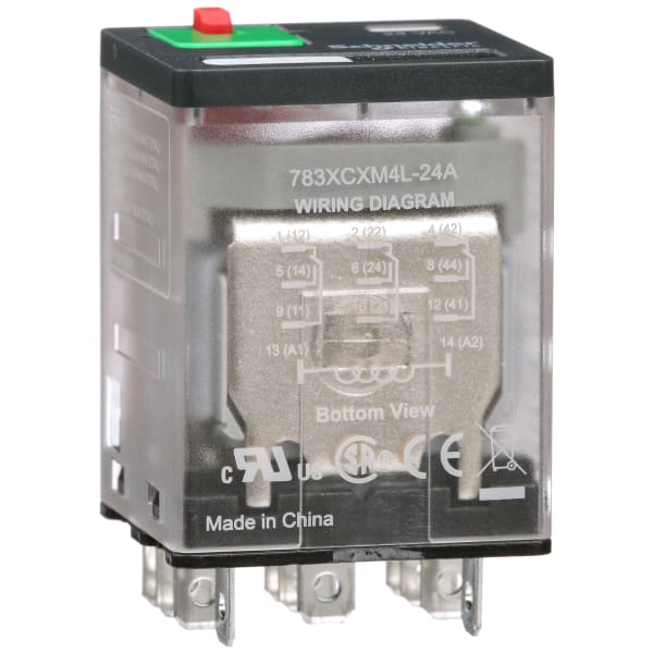
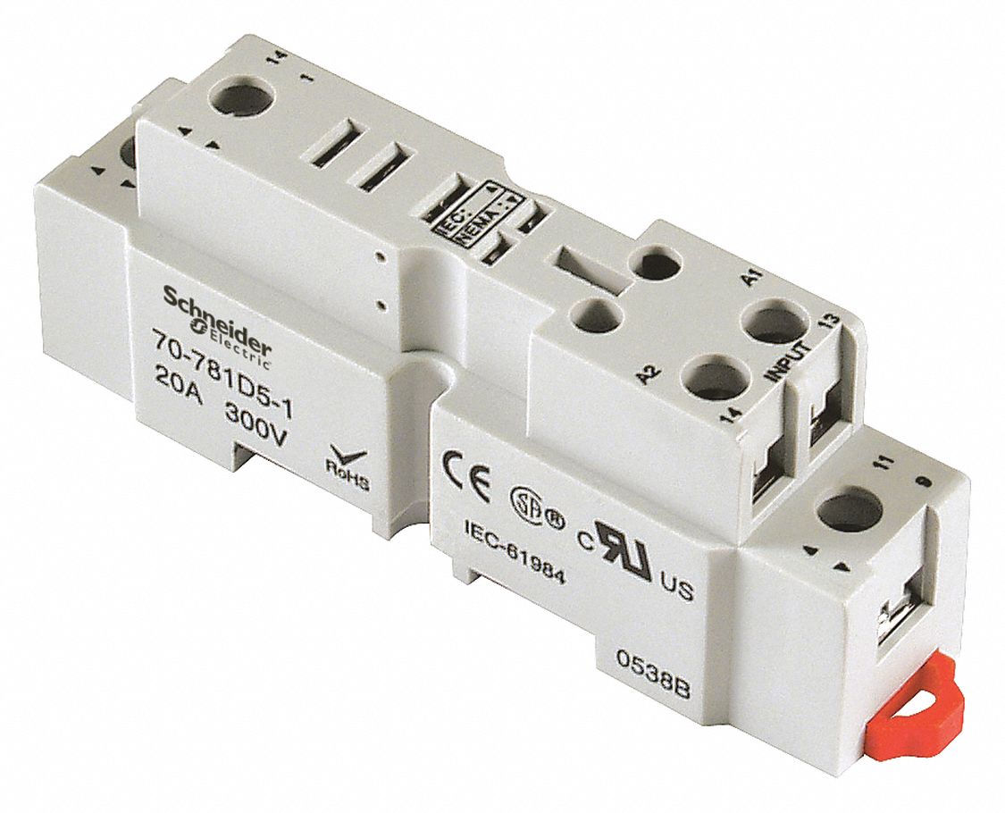
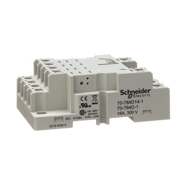
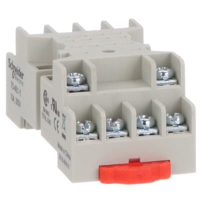
These relays have industry standard wiring and pin arrangements which allows for their use as replacements for many similar relays without wiring or hardware modifications.
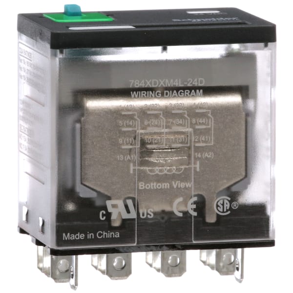
Schneider 14 pin relay wiring diagram.
Page 8 type k plug in relay application data dimensions wiring diagrams contact ratings ac resistive 75 ac type pf continuous hp volts amperes 1 120 240 120.
4 pin relay 4 pin relays use 2 pins 85 86 to control the coil and 2 pins 30 87 which switch power on a single circuit.
Pilot light option available on types kp and ku.
In this video we explain 14 pin magnatic relay.
The wa4 mechanical latching unit for af tactors can be easily converted into compact latched contactors.
Hvac fan relay wiring diagram download.
35 5 0 24 6 0 0 83 21 0 0 24 6 0 full feature cover dimension clear cover dimension dimensions inches millimeters wiring diagrams 11 13 a1 5 9 14 12 1 21 a2 14 6 10 24 22 2 31 41 7 8 11.
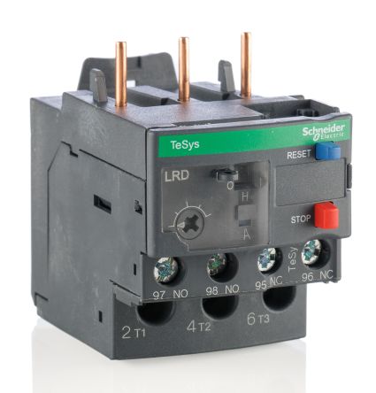
Overload relays ac motors dc motors wiring capacitors resistors.
Here is a picture gallery about 14 pin relay wiring diagram complete with the description of the image please find the image you need.
This creates a basic memory function the relay remembers.
Internal pilot lights are available in both.
Normally open or normally closed.
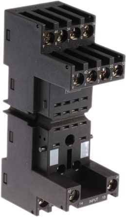
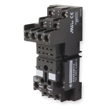
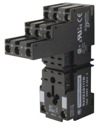
14 pin relay base wiring diagram finder 14 pin relay socket diagram in this post you will learn about the 14 pin relay base wiring diagram.
There are 2 types of 4 pin relay available.
12 volt wiring diagram best 12v relay pin 5 and roc grp org in.
Best bosch relay wiring diagram 5 pole electrical outlet symbol 2018.
In 14 pin magnatic relay two points is for relay coil and 4 common point 4 normally close point 4 normally open point so by this relay we can.
Wiring diagrams magnecraft general purpose relays 792 control series.
Omron 8 pin relay diagram omron 8 pin relay wiring diagram wiring in 14 pin relay wiring diagram image size 444 x 464 px image source.
Wiring diagram book a1 15 b1 b2 16 18 b3 a2 b1 b3 15 supply voltage 16 18 l m h 2 levels b2 l1 f u 1 460 v f u 2 l2 l3 gnd h1 h3 h2 h4 f u 3 x1a f u 4 f u 5 x2a r power on optional x1 x2115 v 230 v h1 h3 h2 h4 optional connection electrostatically.
14 class 2512 and 2520 14.
A normally open relay will switch power on for a circuit when the coil is activated.
Stocked relays table above and insert as shown in how to order.
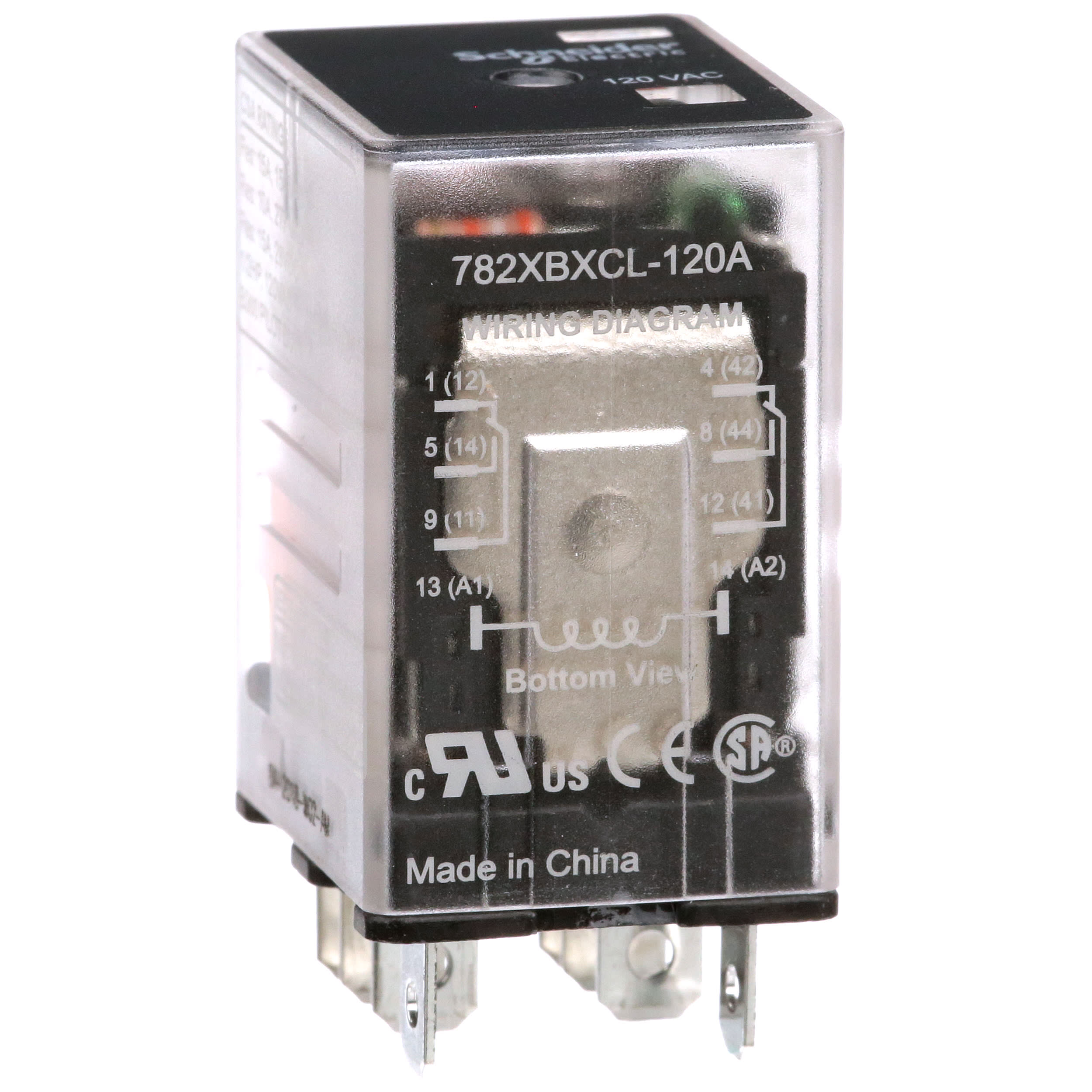
As i said above that in relay we have 14 pin which is numbered form 1 to 14.
On the relay we have the wiring diagram in which all terminals shown with its working principles.


